LIBS Instrument autofocusing system
This chapter explains a cheap innovation for LIBS autofocus system. required to control a LIBS scanning system. A distance sensor to do autofocus by measuring the angle from which the LIBS-laser is visible. This design was inspired, and is basically a simpler improved version of a LIBS autofocus system presented by Cáceres et al. Cáceres, J.O. et al. (2017) ‘Megapixel multi-elemental imaging by Laser-Induced Breakdown Spectroscopy, a technology with considerable potential for paleoclimate studies’, Scientific Reports, 7(1). Available at: https://doi.org/10.1038/s41598-017-05437-3. . We have used this design in our scanner to do measurements over multiple years now and it has proven to be a robust well working sensor.
The autofocus setup using the position sensitive detector(PSD) works so that it measures the angle of the incoming light. We set a lens at an angle to the measurement spot and the PSD behind it. The incoming light, either from reflected laser or from LIBS spark, bends up or down when going through this lens. The PSD gives a voltage proportional to which part of the sensor the light hits. A microcontroller reads the PSD voltage and runs a motor to move measurement head up or down to reach optimal focus. See the figure below the optics principles and video(TODO) and photographs(TODO) of the setup
This is a cheap and easy way to build a LIBS autofocus system. We use the LIBS laser itself as the light source for this distance measurement to make it even simpler.
The setup as it is benefits if a continuously many pulses per second shooting laser is used as it requires the laser as part of the distance measurement. An alternative design could use another light source and is recommended if you either have a slower laser or don't want to damage your samples with any extra laser pulses.
Figure showing the principles (optics) 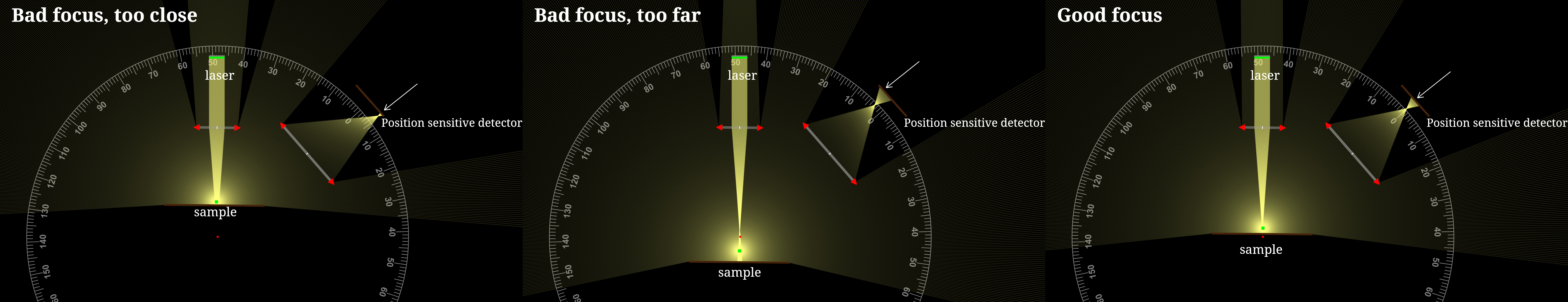
TODO: Video of the autofocus in action
Component list
optical pipe
2 lenses
Hamamatsu PSD position sensitive detector
2 OP-AMPs and a few resistors
piece of circuit board cut to a circular shape that fits in the optics pipe
TODO: Electronics drawing made with Fritzing
TODO: Photo of the electronics
TODO: Photo of the sensor