| INDEX |
|---|
| QShock |
| Results |
| Public. |
| Model |
| SECTIONS |
|---|
| Introduction |
| Simulations |
| Results |
| - Figures |
Stochastic particle acceleration
|
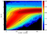
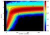
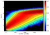
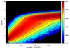
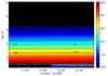
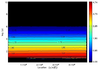
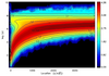
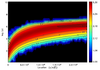
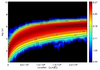
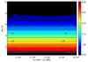
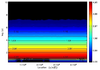
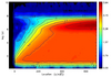
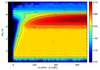
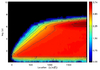
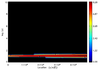
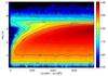
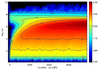
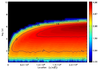
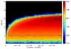
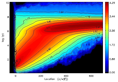
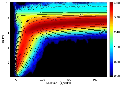
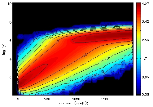
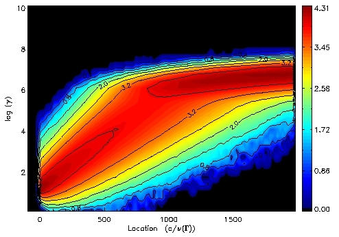
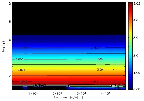
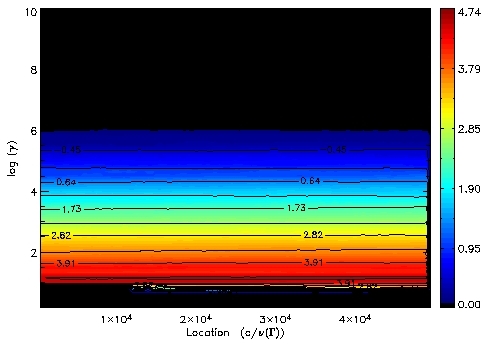
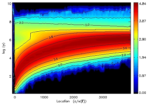
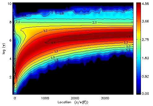
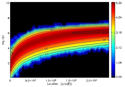
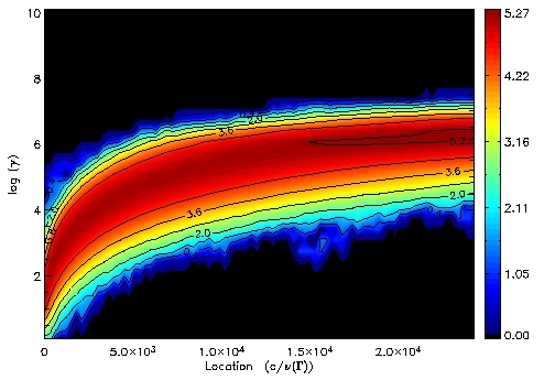
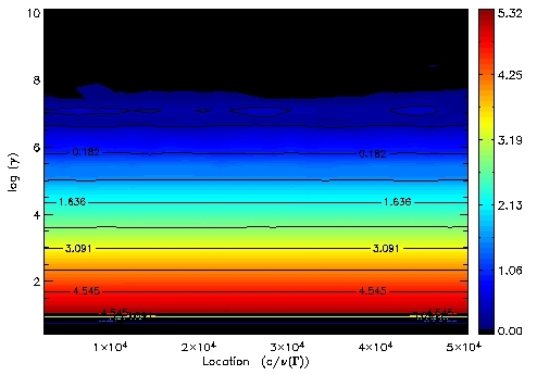
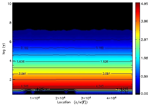
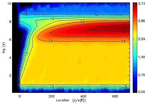
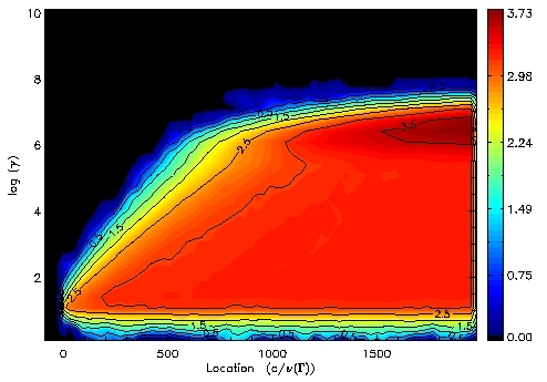
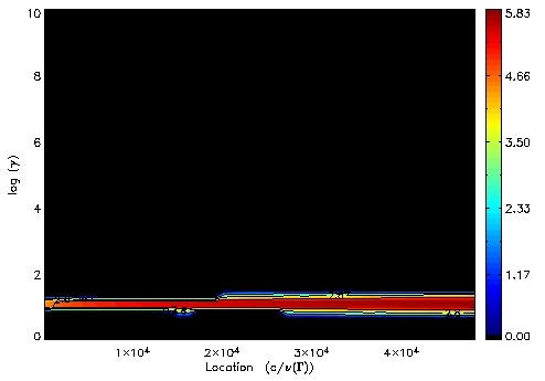
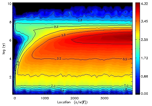
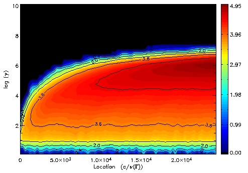
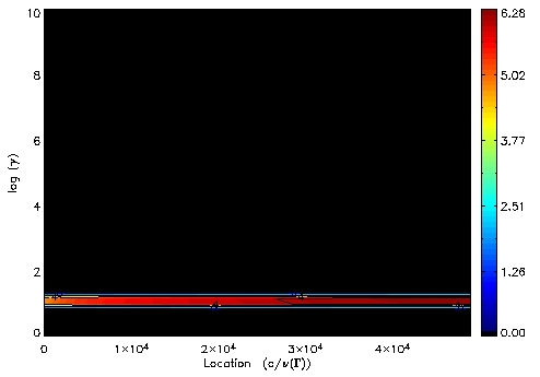
IntroductionWe have applied the QShock code for stochastic particle acceleration in the downstream region of a relativistic parallel shock. These results are part of a larger study, published in the Astrophysical Journal (Virtanen & Vainio 2005, ApJ 621, 313; see astro-ph/0411184 or AAS abstract), where also the discussion and conclusions of these results are presented. (Here only a brief description of the simulations is given.) We have considered the effect of stochastic acceleration to (i) non-thermal particle population, already accelerated at the shock via the first order mechanism, and (ii) particles injected in the downstream region only. Simulations have been run separately for low, medium and high Alfvénic Mach number shocks (M=3, M=10, and M=1000, respectively) and for four cases of downstream turbulence; for turbulence spectral index q = 2 and q = 5/3 with downstream wave field calculated using wave transmission analysis, and with downstream forward and backward waves being in equipartition. The proper speed of the shock is u1 = 10 c in all simulations. SimulationsIn figures below are shown the evolution of the test-particle spectra in the turbulent downstream due to stochastic acceleration. Particles are initially injected and accelerated at the shock front, located in the left edge of the plots. Contours of log( E (dN / dE ) ) show the steady-state particle energy distribution in the simulation downstream. The effect of stochastic acceleration on particles that have been already accelerated at the shock was studied by injecting particles into the shock and the first order mechanism, and allowing them to continue accelerating via the stochastic process in the downstream region. Injection of the particles took place in the downstream immediately after the shock, and particles were given initial energy of a few times the energy of the thermal upstream particles as seen from the downstream. In the second approach was to assume a constant injection mechanism in the downstream and see what happens to particles leaving the thermal bulk flow and starting to accelerate stochastically. (Physically, this models a case, where turbulent fluctuations cascade to higher wavenumbers and inject the thermal electrons to the stochastic acceleration process.) We injected particles with constant energy -- corresponding to the energy equal to the energy of upstream electrons as seen from the downstream region -- isotropically within the whole downstream region. For clarity the simulations are divided into subgategories as follows:
ResultsHere are shown the results of the simulations. Shown on the left-hand panels are the results for which the downstream wave field was calculated as described in Model section (link); on the right-hand panels equipartition of the forward and the backward waves is assumed. First (the first three rows) show results with magnetic field turbulence spectral index q = 2, and the next three show results with q = 5/3. The Alfvénic Mach numbers are M = 3, 10, and 1000, from top to bottom, respectively for each case. First the case of particles injected at the shock, and then the same for the case of downstream-injection. The proper speed of the shock is u1 = 10 c in all cases. (Click 'JPG' or 'PS' links next to each figure to view/open/download larger figure either in jpg or postscript format.)
Copyright © Joni Virtanen & Rami Vainio
Figures reproduced by permission of the AAS. Last modified 27 Feb 2005
|
|||||||||||||||||||||||||||||||||||||||||||||||||||||||||||||||||||||||||||||||||||||||||||||||||||||


